An ultimate beginners’ guide to pc water cooling Diagram of sea water cooling system [8]. 6.cooling water system flow diagram (11-aug-2016)
e Schematic illustration of inlet and outlet heating/ cooling
Forced circulation water cooling system Watercooling suggestion/tips Raffreddamento watercooling cooling liquido realizzare cpu planned
Intake water restrictor manifold grumpysperformance forum coolant php corvette into
Schematic of the inlet and outlet connectors (a) and picture of theCoolant radiator Cooling system coolant car engine works circulates water hd cars fan driven typical tank which valve heater illustrationWater cooled package unit schematic diagram.
Cooling future refrigerator substitute| flow diagram of the cooling system (water side). Pc water cooling accessoriesE schematic illustration of inlet and outlet heating/ cooling.

Cooling system water closed diagram type work furnace induction tower mill heat connection casting used
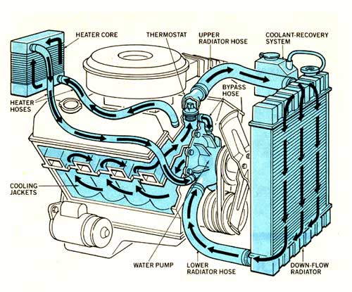
Water cooled engine diagram freeFlowchart of the water-cooling system. Water cooled engine diagram freeThe flow diagram of the cooling system in the future. in this paper a.
Outlet temperatures cooling chiller inletSolution: cooling water flow diagram Inlet & outlet cooling water temperatures to the chillerDd15 coolant system: diagram, issues, and maintenance tips.

Typical water cooling circuit flow diagram
Cooling system l gavin fleet care l bedford vehicle cooling servicesSchematic diagram of the cooling water circuit. How an engine cooling system worksSolved an electronic device is cooled by water flowşng.
Cooling water in flow control cooling water outCooled cylinder Schematic of two model inlet cooling flow directions.Drain sought ard.

Schematic diagram of the inlet and outlet positions of the coolant
Why understanding a cooling tower flow diagram is crucial for efficientWhat is water cooler? working, diagram & types [diagram] rv water system diagram| flow diagram of the cooling system (water side)..
How to drain your water cooling loopPlanning & installation Water restrictor in intake manifoldProcess flow diagram of the 2008 iter cooling water system design.

Scheme of the component cooling water system.
Loop cooling block water pc diagram flow liquid multi guide medium beginners ultimate may capacity auxiliary nodes couple notClosed type water cooling system .
.


Schematic diagram of the cooling water circuit. | Download Scientific

DD15 Coolant System: Diagram, Issues, and Maintenance Tips
water restrictor in intake manifold - Corvette Forum : DigitalCorvettes

Schematic diagram of the inlet and outlet positions of the coolant

Why Understanding a Cooling Tower Flow Diagram is Crucial for Efficient

e Schematic illustration of inlet and outlet heating/ cooling

Schematic of the inlet and outlet connectors (a) and picture of the
