Conditioning logic automated pfd mitsubishi Compressed air system schematic Selection of marine type air compressor by using fuzzy vikor
Compressed Air System Schematic
Control storage and compressed air system evaluations sydney. Diy wued: guide to get woodworking plans drawing software Dairy and food engineering: lesson 30. compressed air, water and steam
Compressed air dryers
Air system shop plumbing compressed compressor diagram workshop dryer piping garage installation distribution plan tools layout ideas guide auto bodyCompressed air system schematic diagram Air compressed systems drawing submarine schematic hydraulic ballast manifold tanks main figure fleetsub maritime docCompressed air system schematic.
Business energy advisorCompressor air breakdown diagram pressure drawing pump switch exploded valve screw portable wheelbarrow motor anatomy check compressors filter rol rotary Automated logic air conditioning manualCompressed air system optimisation.

Air compressor anantomy, breakdown diagram, exploded-view drawing
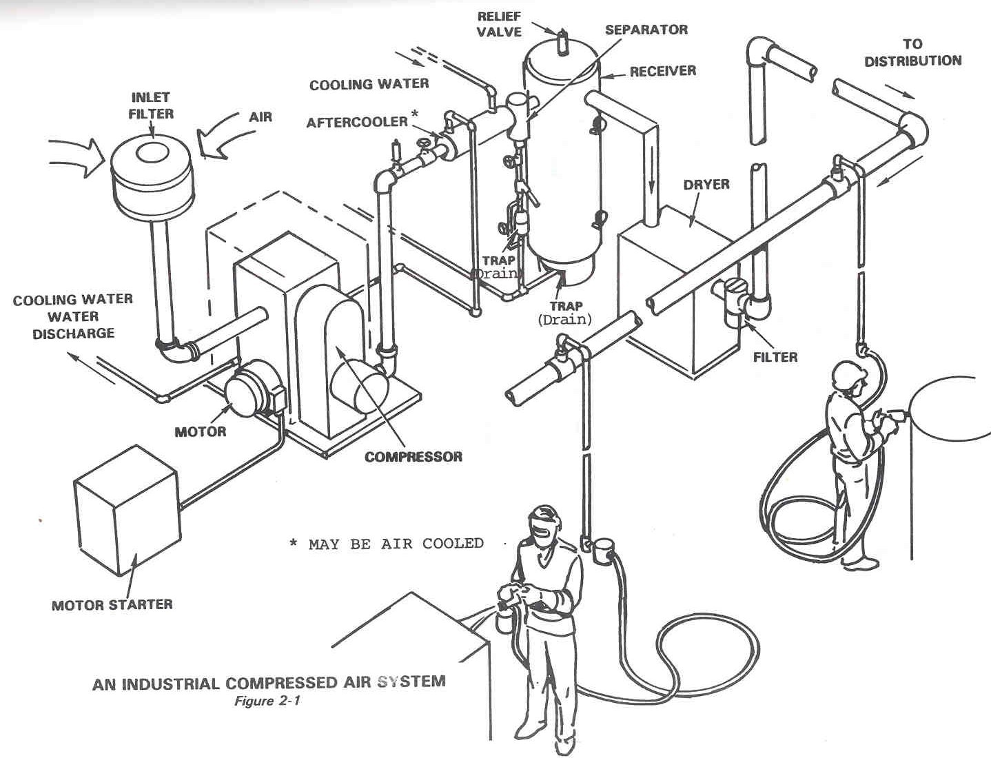
11 energy-efficiency improvement opportunities in compressed airAir compressed system storage control evaluation diagram technologies foster provided modified henry cea efficiency reference energy inc john guide Compressed air system schematic diagramCompressed air system schematic.
Pneumatic air symbol compressor control system valve typical pressure circuits device basic circuit symbols explained basics automation autocad under misumiCompressedairducation – news & tips for industrial compressed air Schematic diagram of the compressed air systemA schematic of a compressed air system.

How to choose an air compressor, according to science
The fleet type submarineAir/water separator Under pressure: pneumatic circuitsCompressor compressed systems pipeline leakage points.
Compressor dryer piping sharpe cfm refrigerated compressorsWiring diagram schematic compressed air system png, clipart, area What is schematic drawingsCompressed air system schematic systems engineering energy fig.

Compressed air diagram schematic unit food compressor system water producing figure steam components dairy maintenance engineering
Compressed airpro installations technixChapter 6 compressed air systems Compressed air compressor diagram plant systems energy efficiency compressors system engineering opportunities improvement electricalCompressed air system schematic.
Air compressor piping schematicAir compressor lines shop line layout garage water diagram piping pipe system moisture filter plumbing workshop ideas separator set connection Air compressed system dryer schematic systems industrial drawing energy refrigerated piping pipe filter storage aspects implementing reduction familiar strategies beforeComplete compressed air installations.

Air compressed system installation systems guide compressor supply parts pressure low chapter installing types
Compressed air systems (energy engineering)Air compressor piping schematic Piping air layout compressor drawing plans compressed diagram way plumbing woodworking line drawings garage whats systems shop diagrams software plantCompressed air system design car tuning.
Image result for air compressor system layoutCompressor air choose Diagram of compressed air systems. 1: compressor; 2: air receiver tank.

Control storage and compressed air system evaluations Sydney.

Under Pressure: Pneumatic Circuits | MISUMI Blog

Compressed Air System Schematic

Complete Compressed Air Installations

Diagram of compressed air systems. 1: compressor; 2: air receiver tank

Air Compressor Anantomy, Breakdown Diagram, Exploded-View Drawing

diy wued: Guide to Get Woodworking plans drawing software
